No products


 Engine running-in - Max Power -
  Preparing your Xray NT1: Part 2
  How to prepare your XRAY NT1 for a race
 Preparing your Xray NT1: Part 2
Published : 2020-11-27 10:13:59
Categories :
Introduction
For those who have already completed the first part of the preparation of your XRAY NT1, you will find here the next step with: shock absorbers and electronics. Otherwise, start with the first article to get the first steps...
The shocks
In this section, we will see step by step how to prepare the shock absorber in the best way and in an evolutionary way to maximize the handling of your car.
Step 1 :
Disassemble the shock absorber, drain the oil and clean everything.
Note: If your oil is black during disassembly, it is dirt that has lodged at the location of your O-ring. In this case, remove the nut, remove the O-ring and clean everything.
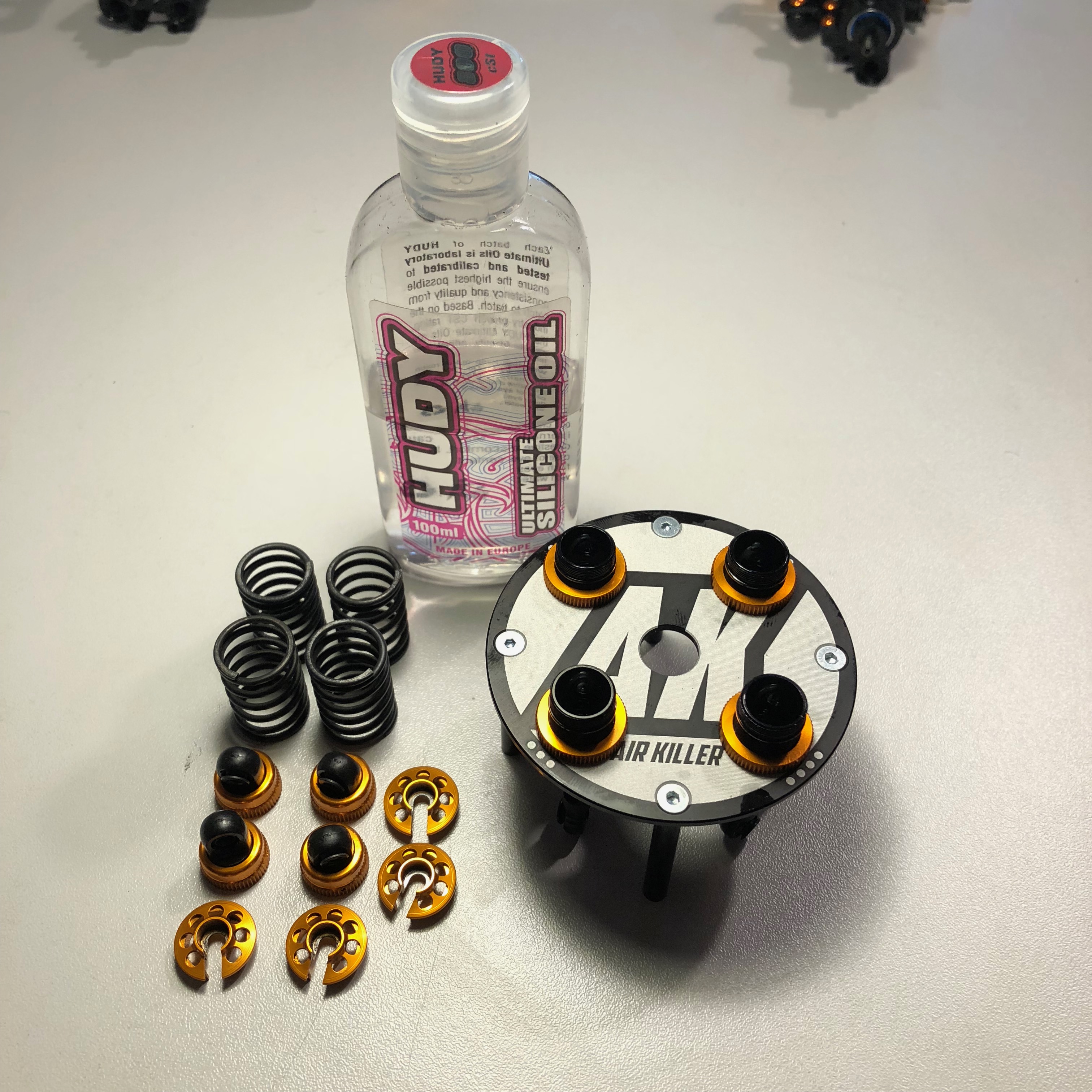
Step 2 :
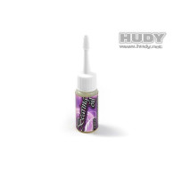
Fill your shock absorbers with the oil viscosity of your choice up to 0.5 mm below the limit of the shock body.
I recommend Hudy oil with which I have never had consistency problems.
Step 3 :
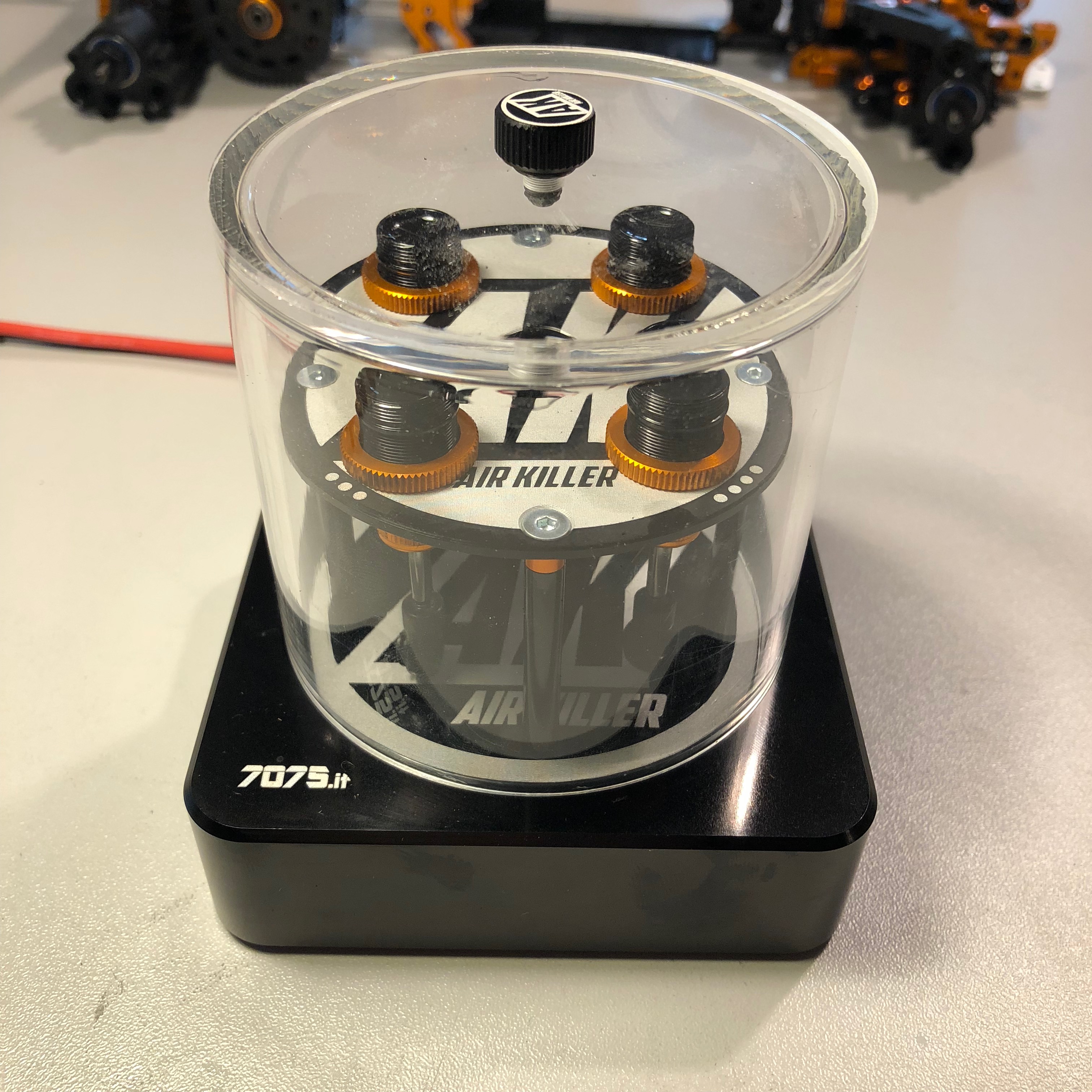
I then use an automatic vacuum pump to eliminate all air bubbles present in the oil in order to obtain the most homogeneous shock absorber possible.
This pump can also be used for differentials, which is very practical given the much higher viscosities and the fact that bubbles are even more difficult to remove.
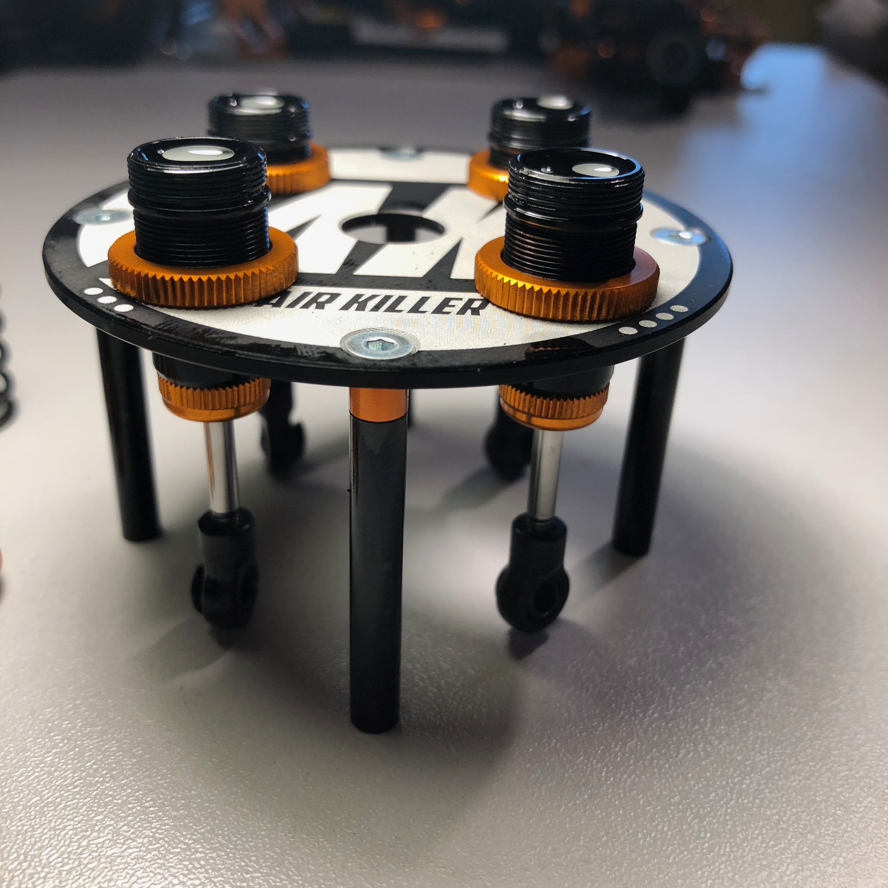
Step 4 :
Once all the bubbles have been eliminated, you must now adjust the rebound which corresponds to the shock absorber decompression. It is possible to adjust the output speed of the rod and its percentage of output.
In 90% of the cases, I use an output percentage of 10%. We will see how to get this value.
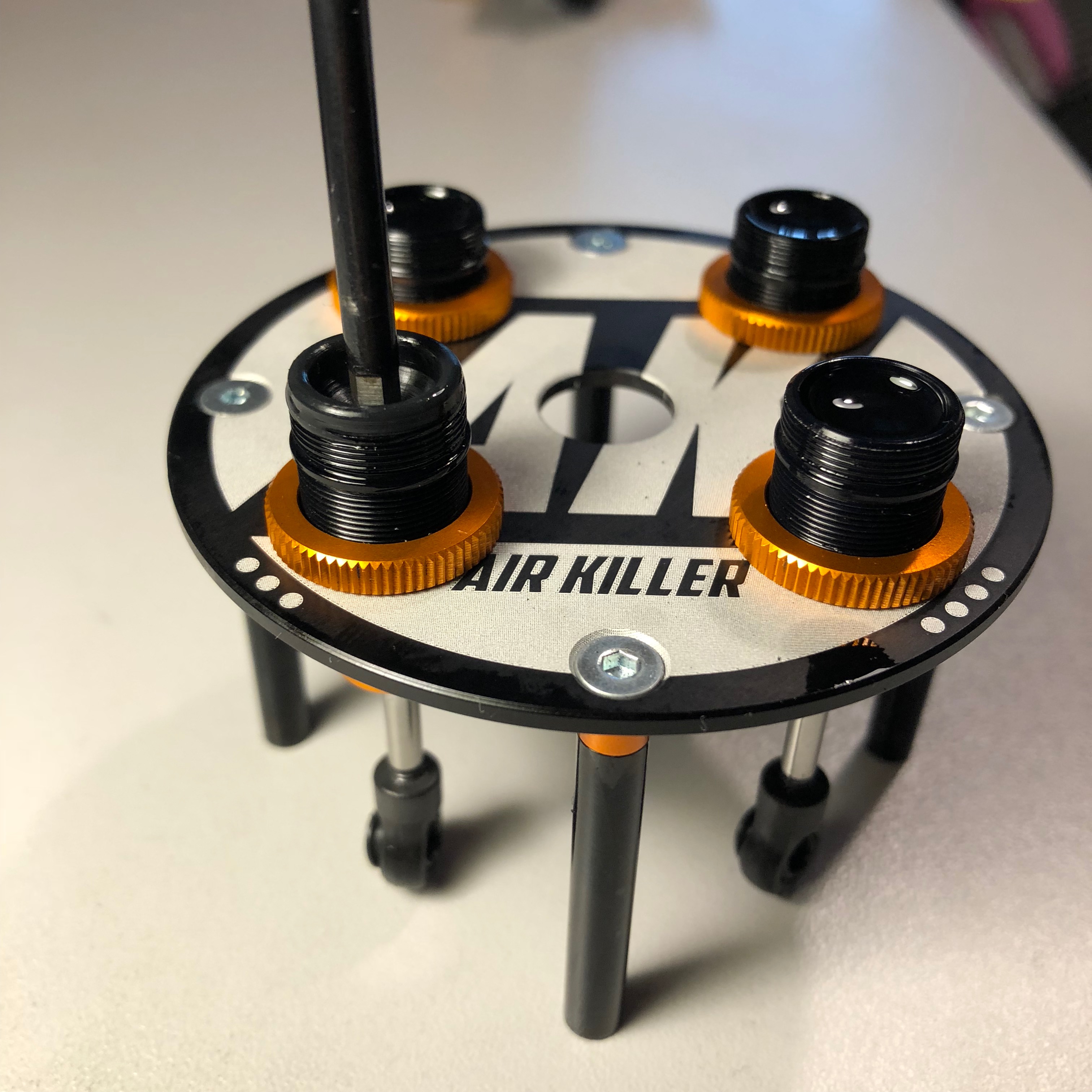
1) Remove the registers from the vacuum pump.
2) Put the membrane in place and press down with a screwdriver to remove excess oil (bottom left photo).
3) Push in the rod until you have 1 mm between the joint and the nut. (Photo bottom right)
4) While locking the rod in position, take the screwdriver back and press on the diaphragm to drain off the excess oil.
5) Close the register
Repeat this procedure so that the other three shocks have exactly the same rebound and thus have the same handling on the right or on the left.
 |  |
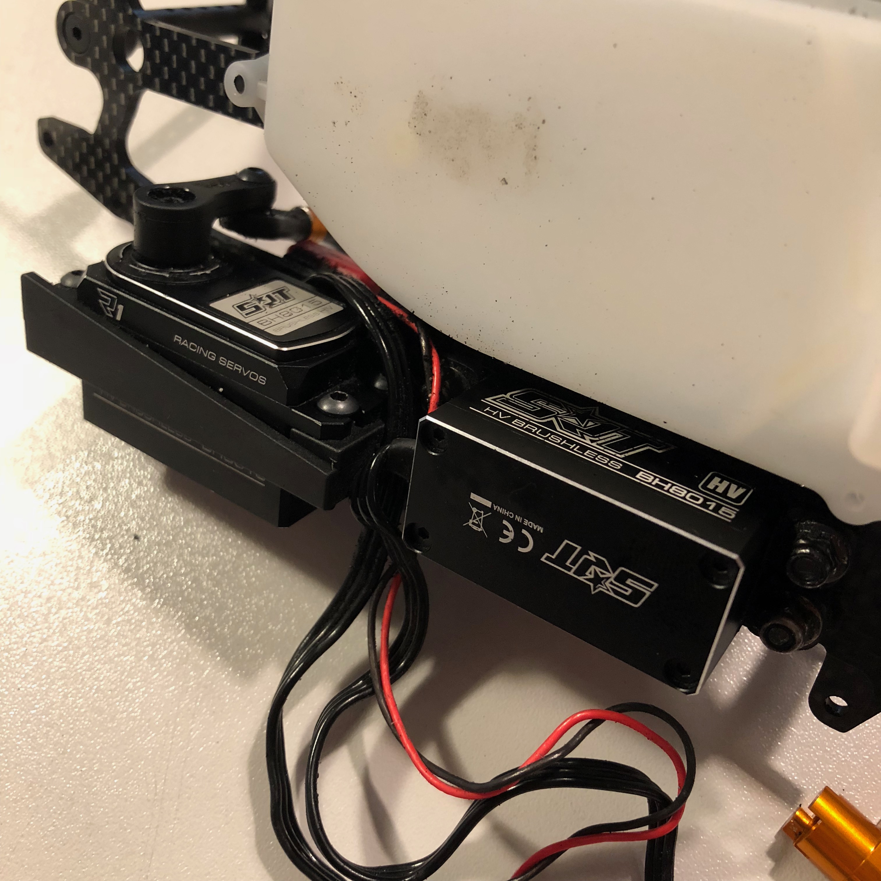
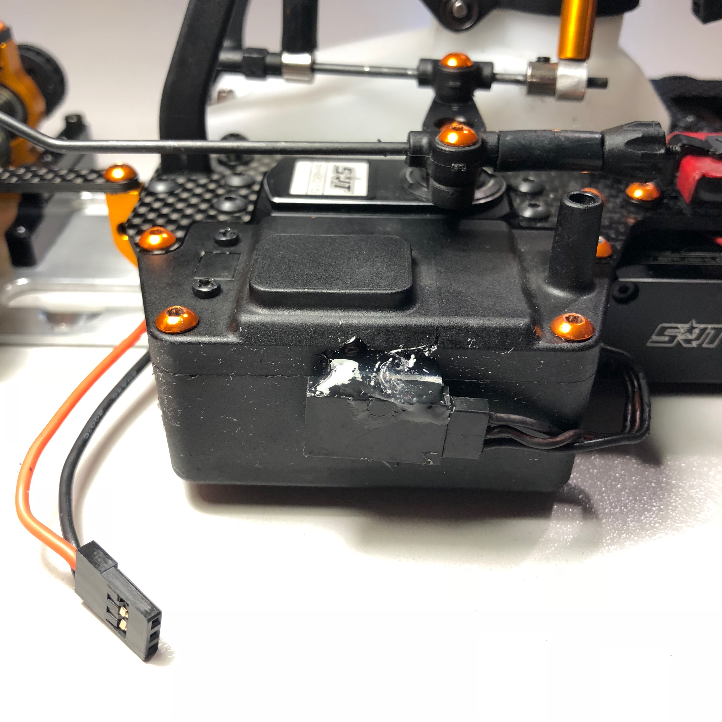
Electronics
The receiver battery
Let's start with the receiver battery.
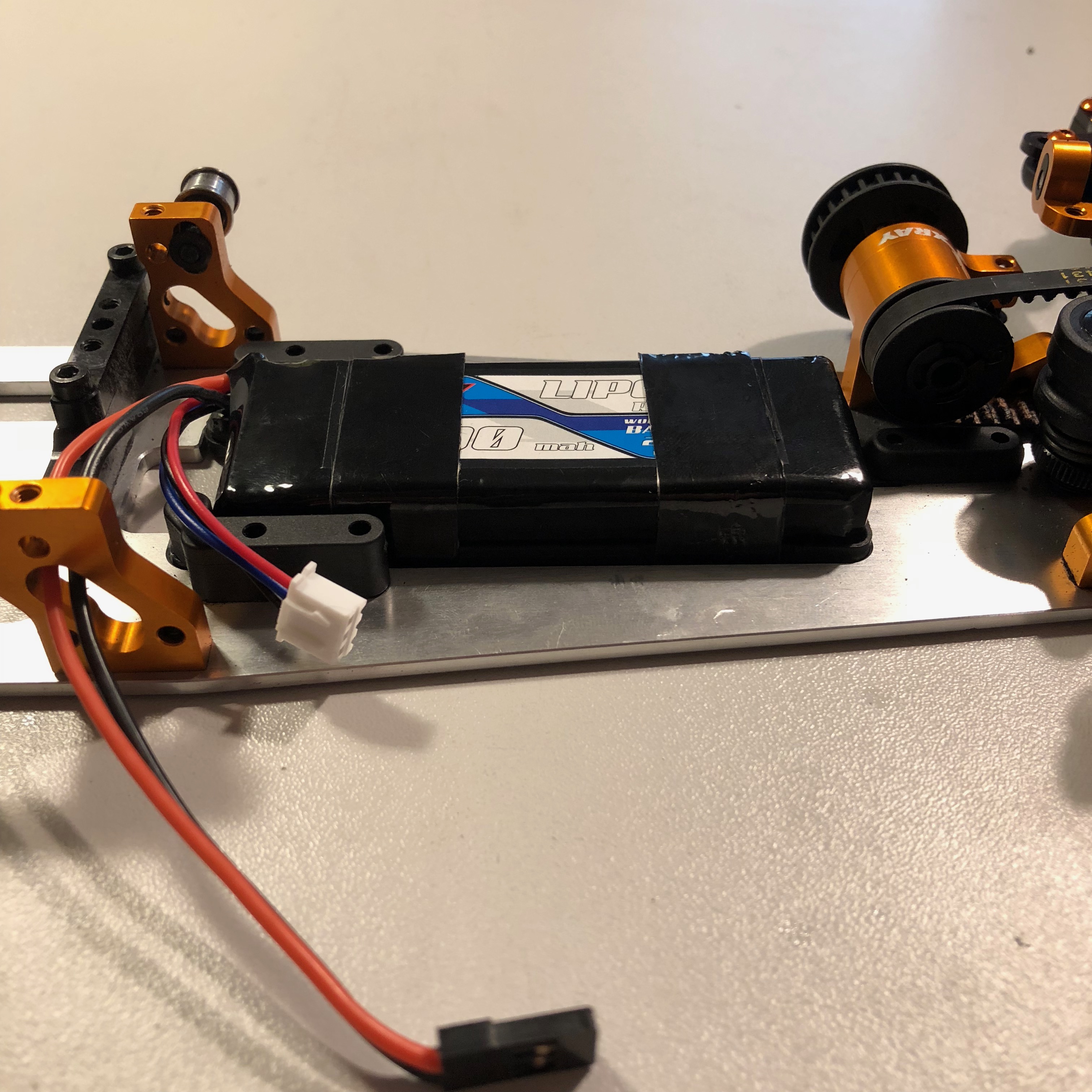
I use a 1500 mAh LiPo battery. The capacity is sufficient for long finals.
The battery I use is extremely flat, only 11 mm thick which allows you to use the tank in a lower position and thus lower your center of gravity. Very useful when you know that with a full tank you have 75g more corresponding to 5% of the total weight. Lowering it by 4 or 5 mm can only be beneficial.
As the battery is less thick, it is a little longer. So you have to sand the left battery holder with a Dremel as on the picture below so that the cables can be perfectly free.
Put the battery in place and use a reinforced battery strap to secure the battery. With this strap, you can be sure that the battery will never come loose.
The radio plate
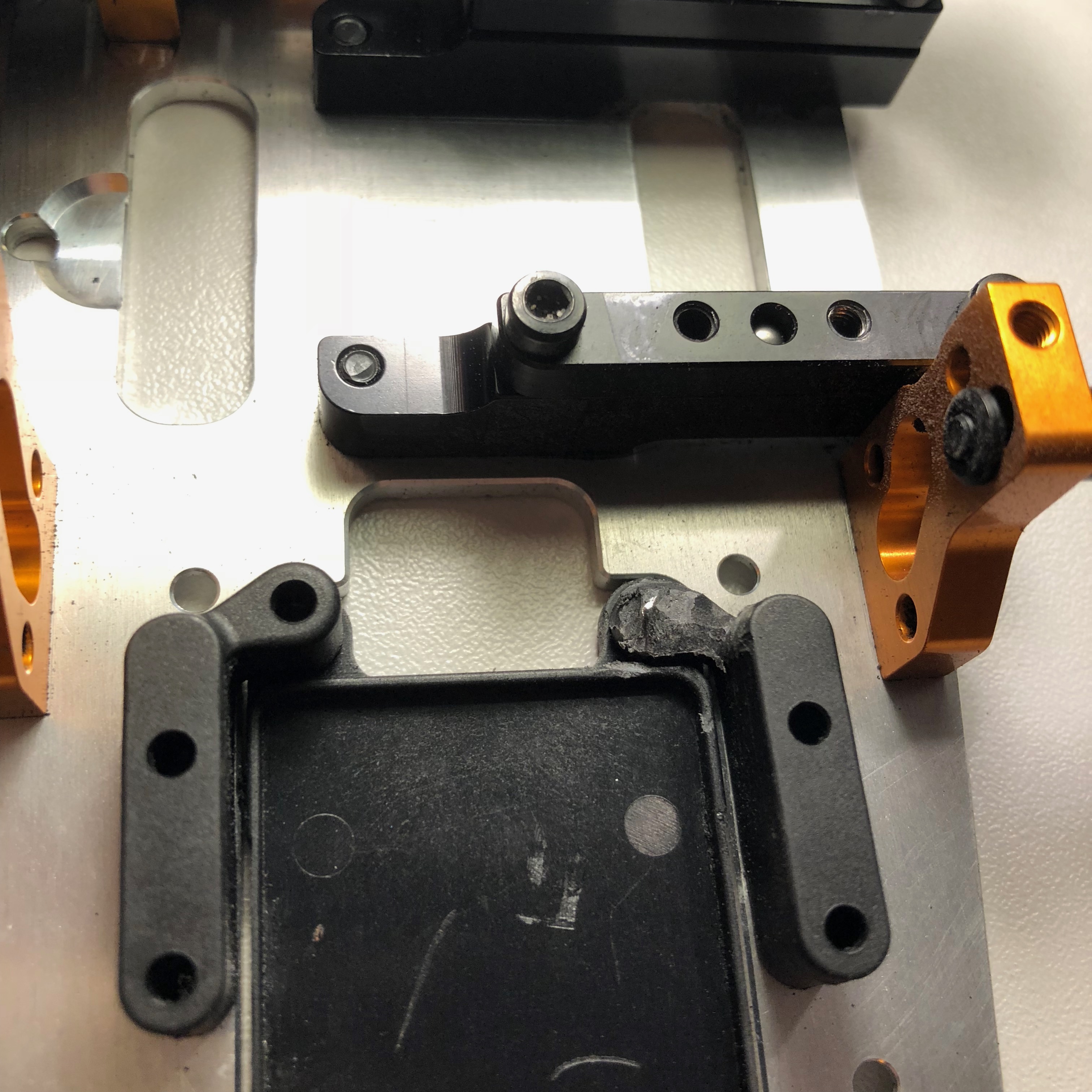
To have a clean electronic assembly with no risk of cut cables, here is how to do it:
-Thread the steering servo and transponder cables between the radio control board and the steering servo bracket to bring them out between the throttle servo and the steering servo.
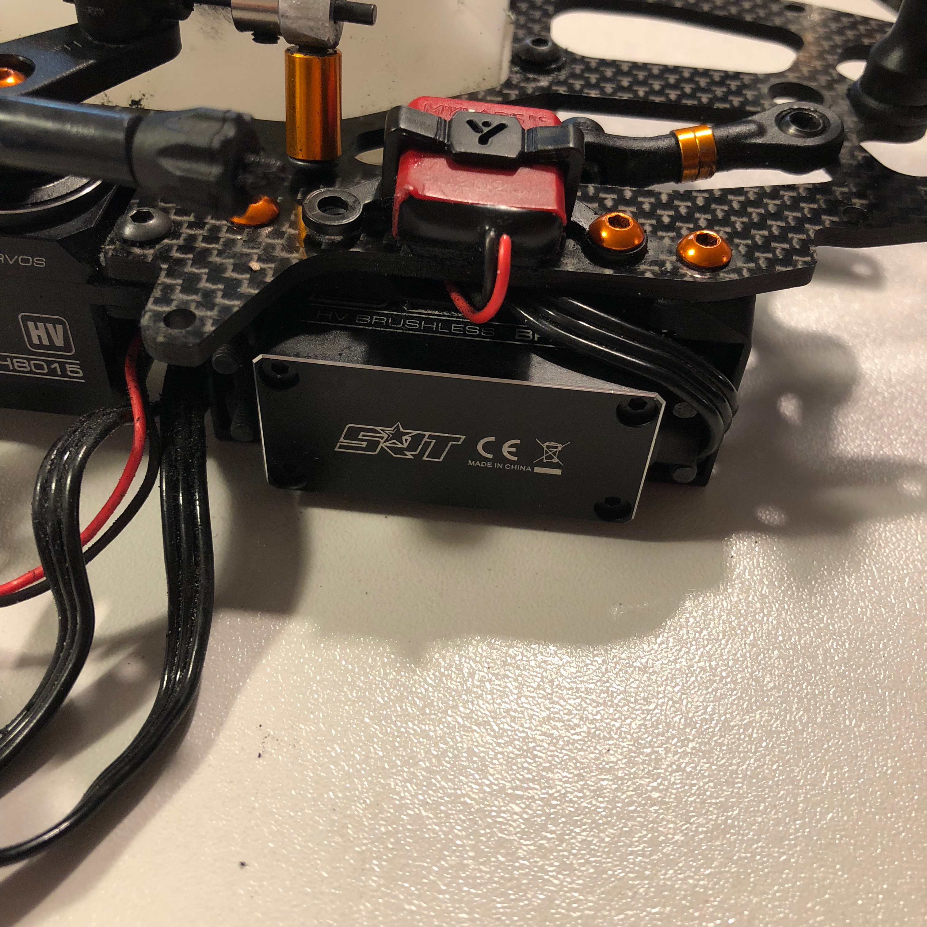 |  |
-Connect your cables to your receiver
-Close the box
-Attach the power cable to the radio box using the HUDY body mount to secure the attachment.
Throttle linkage and steering linkage
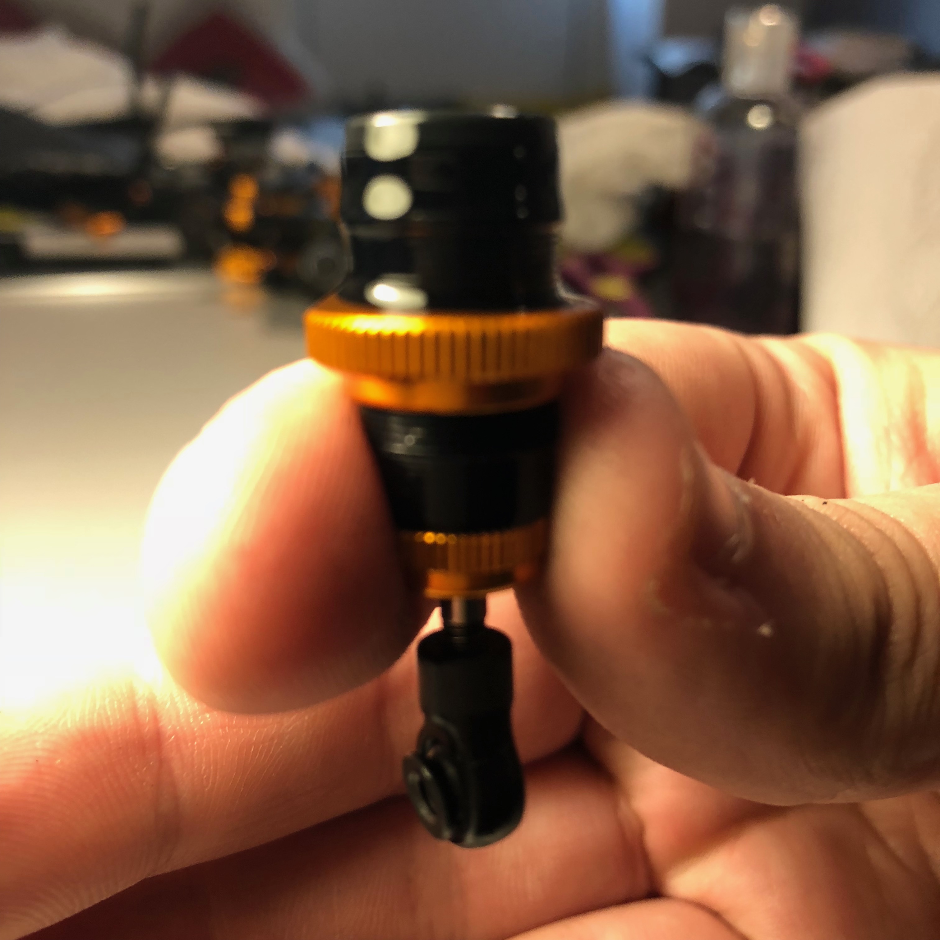
On the throttle linkage, I secure the gas stop with 2 stops. On the second one, I put a round-head screw to open the carburetor when starting the engine without radio control.
Against the carburettor gasket, I also mount a stop with a round head screw with a piece of fuel tube to position the carburettor rubber band. The fuel tube will not attack the elastic on the threads of the screw.
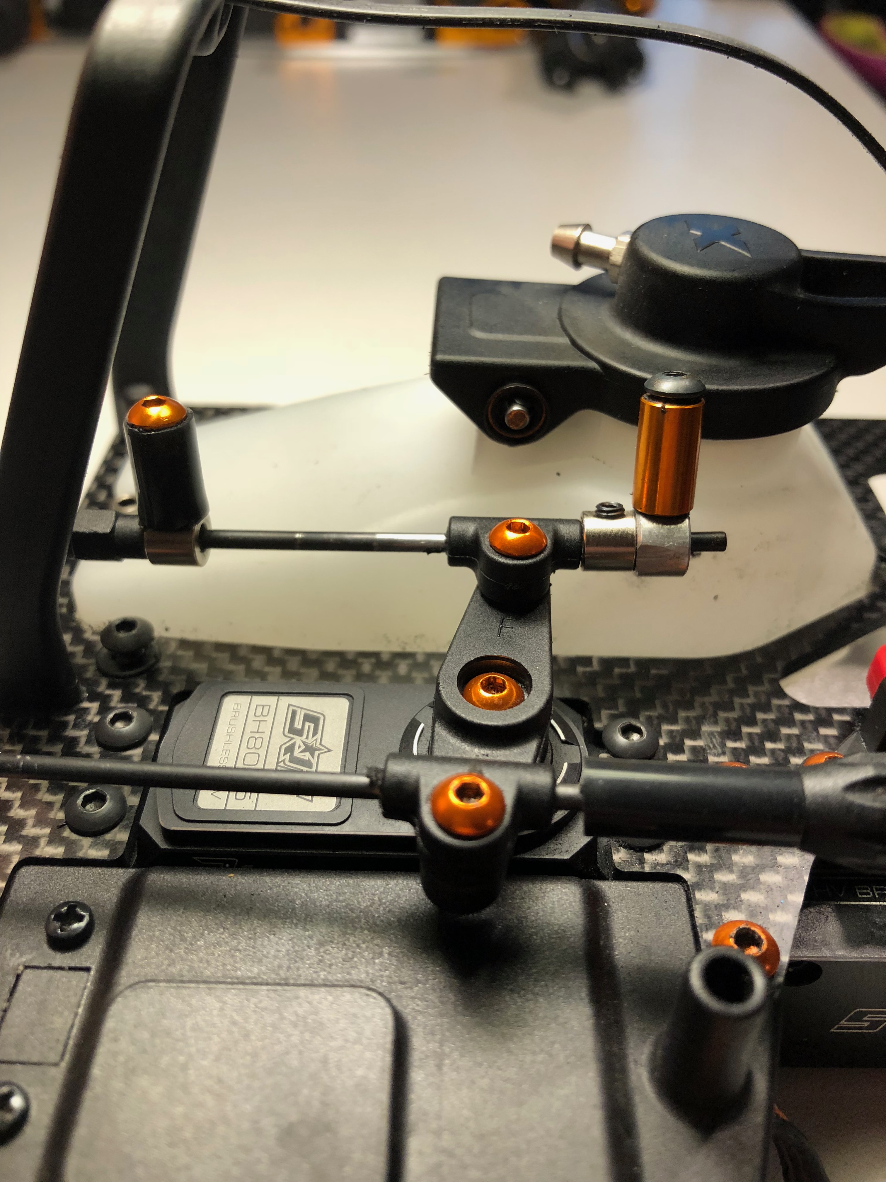
Concerning the steering rod, in order to have the optimal setting so that the steering horn is at 90° when the wheels are neutral, I put 4mm between the two joints, where the two orange washers are located.
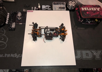
We have now completed the preparation of the chassis!